![]()
![]()
![]()
|
|
|
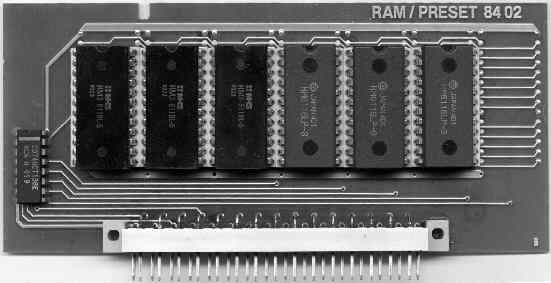
| PRK Sound CardSince not every PRK comes with the sound cards, as I had to find out recently, I volunteered for the task to recreate the sound cards, titled RAM/PRESET 84 02 in the original. To add the cards, the PRK has a series of connectors. These connectors are filled with up to seven sound cards. Card dimensions
The original cards have a size of 145x64mm. The width isn't critical and can be reduced down to a minimum of 85mm. The height must be correct, since the board is fixed in the PRK by a slight deepening in a metal plate. This also means that the traces on the PCB must stop at least 2 mm below the border, a bigger distance is better. The original cards have a deepening opposing pin 31 that has no function. The original PPG cards are filled with 6 or 7 EPROMS, type 27C128 (16Kx8) and an address decoder 74LS138. ConnectorThe necessary connectors are of type DIN 41612/41617 with 31 Pins, 2.5mm spacing. Obviously these connectors are still in production, for example by CONEC. Since the PRK must have at least one card of that type, that holds the static RAM needed to store the PRK programs, I could reverse-engineer the card. The following table holds the connections for both the EPROM cards as well as the SRAM card.
The EPROMs or SRAMs on the card are controlled by the 74LS138 chip. The 74LS138's outputs control the /E input of the following EPROM or /CE input on the card (from left to right):
Chip 1 has the lowest address range, Chip 7 (if there) has the highest address range. RedesignSince far bigger EPROMs have been developed in the meantime, it is now possible to use one EPROM instead of the 6 or 7 on the original card, thereby reducing the number of chips on the card from 7-8 to 2. This reduces the costs and complexity considerably. I've begun to design a new card based on the 27C1001 EPROM (128Kx8) - Schematics are here. More to come.
| ||||||||||||||||||||||||||||||||||||||||||||||||||||||||||||||||||||||||||||||||||||||||