|
| | PPG Wave / EVU MIDI Retrofit
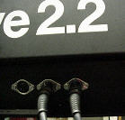
All PPG devices built before 1984 came without a MIDI interface. This is the
case for many of the Waves of type 2.2 and for early EVUs.
When the Wave 2.3 appeared, you had the possibility to upgrade an existing
Wave 2.2 to 2.3. Two of these upgraded Waves are in my possession. During this
upgrade, 8 single outs and MIDI was added, too. The MIDI retrofit consists of a
small add-on board that is plugged into the I/O-82 board:
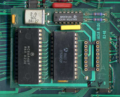 The 6840
chip is removed from the I/O-82 board and plugged into the ACIA MIDI
board. The ACIA MIDI Board is then plugged into the original 6840 socket,
after having been soldered to the I/O- 82 board in two places (not visible
on this picture since it's below the add-on board). The 6840
chip is removed from the I/O-82 board and plugged into the ACIA MIDI
board. The ACIA MIDI Board is then plugged into the original 6840 socket,
after having been soldered to the I/O- 82 board in two places (not visible
on this picture since it's below the add-on board).In my case, the
upgrade has been done by PPG directly and (unfortunately) they adhered to
the recommendation to solder it to the original 6840 socket in some places
to guarantee a greater stability... which didn't exactly ease my analysis
of the board.
|
Using the free socket visible in the picture above, the ACIA MIDI board
is then connected to the I/O MIDI board:
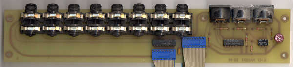 The right
one of the two flat cables leads to the ACIA MIDI board (or, on younger
devices that already come with MIDI, to the I/O-84 board), the left one is
for the single outs and is connected to the motherboard. The right
one of the two flat cables leads to the ACIA MIDI board (or, on younger
devices that already come with MIDI, to the I/O-84 board), the left one is
for the single outs and is connected to the motherboard. |
On this (I/O-84 compatible) solution, the MIDI interface is spread
across two boards and inseparably combined with the single outs. To add it to an
unMIDIfied EVU this is unusable, since it already has the single outs on the
front side.
Apart from that, you can't buy the upgrade any more...
Alternative Solution
To add MIDI to my EVU, I had to go another way. This consisted of a
functional rebuild of the PPG solution. The first step was to reverse-engineer
it and to work out the schematic behind the logic spread across the two boards.
This lead to the following diagram:
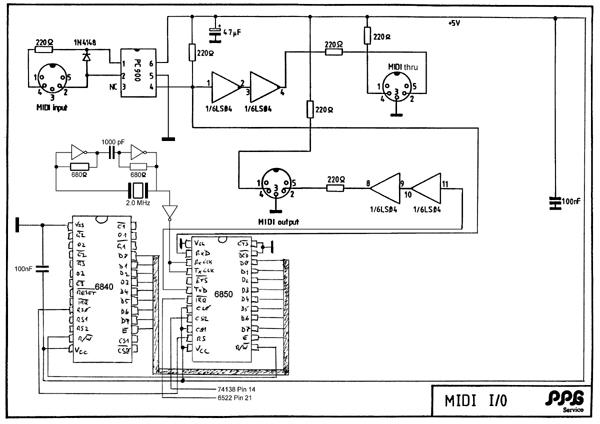
Click here for a big .tif picture in original size or click here for a slightly smaller .gif picture
If somebody finds this familiar, no wonder - one half of that is from
the Wave 2.3 Service Manual.
List Of Needed Materials
 | 4 IC sockets DIL 2x14 17,7mm
(3 if different construction - see "Construction Details" below) |
| 1 IC socket DIL 2x12 17,7mm |
| 2 IC sockets DIL 2x7 10,1mm |
| 1 IC socket DIL 2x4 10,1mm
(actually, a socket with 2x3 pins would be needed for the PC900, but I
couldn't find one) |
| 1 6850 ACIA |
| 1 optocoupler PC900 |
| 1 quartz 2.000MHz |
| 1 capacitor 1000pF |
| 2 74LS04 (or 74S04, 74HC04) |
| 1 elco 47µF |
| 1 diode |
| 6 resistors 220 Ohm |
| 2 resistors 680 Ohm |
| 2 (4) capacitors 100nF
depends on the construction - for the7404 chips, I've used sockets with
built-in capacitors (less soldering; see following picture) |
| 3 DIN sockets type 4 (for MIDI) |
| connection cables in matching length; 2x 3 poles (Thru, Out), 1x 2 poles
(In) |
| 1 strip board (mine's roughly 100x160mm, but depending on your skills, it
might even be smaller) |
The following parts are only needed if my "plug-in" solution is
rebuilt:
| 1 male header 2.54mm 10 pins |
| 1 female header 2.54mm 2 contacts
(connection to I/O 82) |
| 1 female header 2.54mm 8 contacts
(connection to the MIDI DIN sockets)
I used prefabricated cables for that - costs more, but needs less soldering. |
Construction
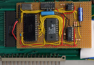
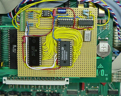
So - then I built it on a 2.54mm strip board. Here's a picture:
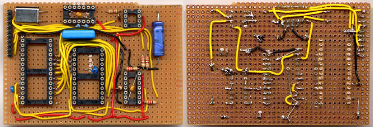
Maybe not the best possible work, but my most ambitious soldering project
till now :-)
I've done the connection to the I/O- 82 board like that:
 The
PPG solution consists of a soldered connection. I prefer solutions that
can be taken apart if necessary and used 2 pins of the male header for
that. The
PPG solution consists of a soldered connection. I prefer solutions that
can be taken apart if necessary and used 2 pins of the male header for
that.
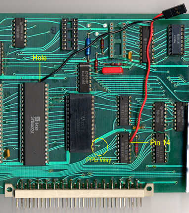
The red cable is directly soldered to pin 14 of the 74LS138. The black
cable is soldered to a hole in the I/O-82 board that's connected to pin 21
of the 6522 (on the soldering side).
PPG had another, functionally equivalent solution: here, an isolated
wire goes through the hole titled "PPG Way" in the
picture on the left and is soldered directly to pin 21 of the 6522 socket. |
|
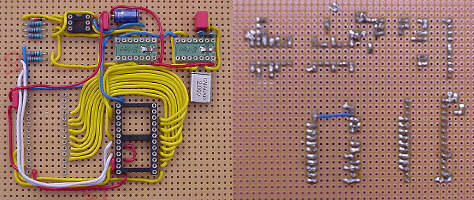
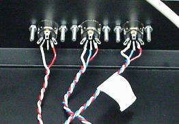
And that's how it looks like when it's complete:
 The 8
pins that aren't connected on this picture are used for the MIDI
connections: In (2 pins), Thru (3 pins), Out (3 pins). I didn't want to
put the whole EVU into my scanner :-) The 8
pins that aren't connected on this picture are used for the MIDI
connections: In (2 pins), Thru (3 pins), Out (3 pins). I didn't want to
put the whole EVU into my scanner :-)
 I
used DIN sockets of this type: I
used DIN sockets of this type:
Paul Maddox recommended against using this type since the metal
shielding might introduce "hum and strange MIDI data" on MIDI In
if an improper MIDI cable is used, it's better to use plastic sockets.
|
Construction Details
An interesting question, especially for non-electronic engineers like me, was
how the base construction was done which connected the MIDI board to the 6840
socket. If you simply solder a normal IC socket to the board, the pins don't
stick out far enough to be plugged into the original socket... I've worked my
way through some catalogues hoping to find a solution to that problem, but
couldn't find anything. Well, there's always a way - I purposely destroyed a
normal IC socket to use the single pins in there.
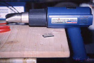 With a hot air gun, this went
quite well - after some time, the socket begins to melt (attention: at
this temperature you can burn wood, so be careful!) and I could extract the pins
with an isolated plier. With a hot air gun, this went
quite well - after some time, the socket begins to melt (attention: at
this temperature you can burn wood, so be careful!) and I could extract the pins
with an isolated plier. |
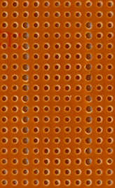 The
next step was a bit easier - the pins have to be submerged in the board so
that they come out far enough to be plugged into the original socket. To
do that, I've carefully widened the necessary 2x14 holes on the board to
1.5mm (see picture on the right). The
next step was a bit easier - the pins have to be submerged in the board so
that they come out far enough to be plugged into the original socket. To
do that, I've carefully widened the necessary 2x14 holes on the board to
1.5mm (see picture on the right).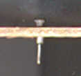 In
these holes, you can easily insert the pins. In
these holes, you can easily insert the pins.
Attention: when soldering the pins to the board, you should use
just the absolute minimum of soldering lead, since the pins have to be
inserted into the socket below them! |
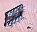 After that a normal socket is put on top of the
single pins. I did it before
soldering - eases the pin alignment a lot. After that a normal socket is put on top of the
single pins. I did it before
soldering - eases the pin alignment a lot.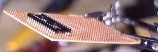
|
 In
theory, using a WireWrap socket instead of the tinkering above should work quite well; a construction of
that kind, however, should be soldered to the socket below, since the pins
stand out about 1cm on the lower side of the board, reducing the
mechanical stability. Alternatively, you could shorten the pins to the
same length, but that means precision work. In
theory, using a WireWrap socket instead of the tinkering above should work quite well; a construction of
that kind, however, should be soldered to the socket below, since the pins
stand out about 1cm on the lower side of the board, reducing the
mechanical stability. Alternatively, you could shorten the pins to the
same length, but that means precision work. |
| If somebody knows a better solution or has a link to existing parts
that don't need such a hassle, please let
me know the details! |
 A
very interesting questions in case of my strip board assembly was how to
solder cables to these pins - this has to be done on the upper side, since
there's no space on the soldering side, this needs to stay free to be
plugged into the socket below. To ensure a stable connection, I've used
specially bended cables and additionally soldered them to the board. This
may be absolute overkill since there should be no mechanical stress on
them, but you never know... A
very interesting questions in case of my strip board assembly was how to
solder cables to these pins - this has to be done on the upper side, since
there's no space on the soldering side, this needs to stay free to be
plugged into the socket below. To ensure a stable connection, I've used
specially bended cables and additionally soldered them to the board. This
may be absolute overkill since there should be no mechanical stress on
them, but you never know... |
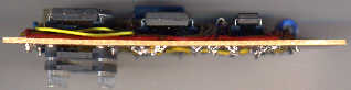 The
whole thing is then plugged into 2 IC sockets, so that it reaches a height
where it can be put on top of the I/O-82 board without touching the ICs
below it. The
whole thing is then plugged into 2 IC sockets, so that it reaches a height
where it can be put on top of the I/O-82 board without touching the ICs
below it.
PPG, by the way, used the same construction. On the original, the
sockets were soldered together at some places to increase stability. |
Usage
OK... that's it. Nearly.... of course, you've got to drill matching holes in
the back plate of the device. Insert the MIDI sockets there, re-assemble the
thing, and off we go...
Or so.
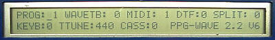
The Waves and EVUs need a new operating system that knows about the MIDI
interface. For the Wave 2.2, this is at least V4.5, for the EVU it's V3. Images
of the necessary EPROMs are available on Paul Maddox' PPG
CD-ROM (Wave V6 only; Wave V4.5 will be on CD-ROM V3).
If you can't burn EPROMs yourself, you can contact
me.
A completely new version of
the operating system that allows exchange of program data with your computer can
be found here.
Before inserting the new EPROMs, you absolutely have to save the
current programs! Depending on the OS version installed before, chances are very
high that the new program data use a different format, which renders the old
program information absolutely useless.
So... if all went well, the device speaks MIDI as soon as you turn it on the
next time.
Costs for the above solution: about 20 Euro (tools not included).
Time needed: well... it took me about a week, reproduction should be faster.
 Others' Solutions
Lars Johansson has done the MIDI Interface. Here's his (not yet completed) design:
As you can see, he invested a LOT of time into an optimal placing of the
elements! And here's the finished product:
 |
Last update: 10/26/03 |
|
|
