![]()
![]()
![]()
![]()
![]()
|
|
|
| This is part 2 of the series "How to convert the
Waveterm into a real computer." How do you convert a Waveterm into a real computer?Well, the first problem - attaching a keyboard - has already been solved. The next important step - it needs the capability to speak to the outside world, not only to other PPG instruments. To reach that, you can activate the serial interface that's an invisible part of the Waveterm. Here's how. Attention: for now, this part and the next one are limited to the Waveterm A and upgraded Waveterm B based on an Eurocom II motherboard, as the later version of the Waveterm B unfortunately doesn't have a serial interface. I'm sorry, folks. Really. CinderellaWhen designing the Waveterm, some unfortunate (in my opinion) design decisions were made - everything not strictly necessary for the use of the Waveterm in the PPG System has been hidden or removed... such as the serial interface. On Paul Maddox' PPG-CDROM, there is, amongst other treasures, a Service Manual for the Waveterm B that contains 3 schematics for the Eurocom II. The scan quality isn't really great, but sufficient for my purposes - I could determine that there had to be a serial interface on the Eurocom, and where. And hoorray - when I opened it, the chip was in place! BasicsThe interface implemented in the Eurocom is an 6850 ACIA. This chip allows to implement a minimal serial interface with only a handful of external components. "Minimal", since only the really necessary control lines are available. These are:
If you consider the "full implementation", as you can find in a PC, the following lines are missing:
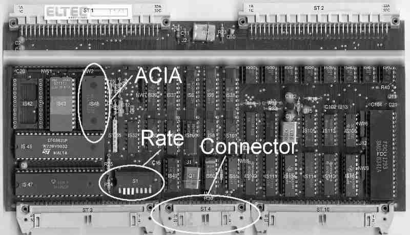
Well... these aren't extremely important anyway. One more's missing in this special case... the Eurocom II creators obviously didn't think that anybody would use a modem with the Eurocom, so they didn't connect the CD line. Boy Scout RomanticismFinding the connector pins used for the serial interface was a very time-consuming task, since it is impossible to take that from the CD-ROM's Service Manual (which is a scan of a copy of a copy of a copy made a long time ago) - so I had to search for the pin layouts of all needed components on the Internet and then had to trace the lines on the board with the help of a happily beeping Digital Multimeter ("call me R2-D2" :-). Anyway - I did it! You Are HereTo ease understanding of the following instructions, here's a slightly reduced picture of the Eurocom, with the relevant parts marked:
Additional HardwareThe serial interface of the Eurocom II V7 is routed to connector ST4. This connector is unused in the Waveterm; none of the signals available there is used. To use it, you need a 26-pin PCB connector for flat cables (plus cable, of course), which can be easily obtained in any electronics store (if you're unsure what to buy... something like that). I'd recommend using about 50-60cm (about 2' for those who only pay lip service to ISO standards :-) flat cable. While the length isn't critical for RS-232, you don't need more. For my interface, I took a part of my PC hardware junk collection - many years ago, when men were still men and PC motherboards were still built in AT format, but already highly integrated, the parallel ports normally were connected using exactly this 26-pin PCB connector. I unsoldered the female DB25-connector from the cable and attached a male connector instead (including cable, using a serial connector from the same deceased PC :-). Now we need a RS-232-connector... these are available in DB25 and DB9 format. It is absolutely unimportant which one you use (provided you have a matching null-modem counterpart). The following lines have to be connected:
I would suggest that you don't cut the unnecessary lines of the 26-pin flat cable too short - there's surely more that can be done with ST4... but that isn't part of this instruction. Perfectionists can use a fretsaw to cut a matching hole into the back of the Waveterm - I've simply let the DB25 connector (shielded in a plastic case) hang out of the Waveterm on the backside; when you tighten the screws of the hood, it's quite secure. Connecting this cable to ST4 is easy - Pin 1 is marked with a little arrow on ST4. If the Eurocom is placed like on the above picture, it's on the right side. SpeedOK, so now we got a line to the rest of the world. How do we get the Waveterm to talk over it, and that in a manner that can be understood? To accomplish this, hardware and software adjustments have to be made. The ACIA is driven by a Single Baud Rate Generator that delivers the frequency. For that, a little DIP switch block is placed on the Eurocom (labeled "Rate" on the picture above). Seen from the front side, it has the following standard settings (provided the former owner of my Waveterm hasn't fiddled with it :-):
The baud rate is adjusted with switches 1-4. Wolfgang Schwotzer, creator of the FlexEmu 6809 emulator package, kindly provided their settings to me. Additionally, the ACIA can be programmed to divide the input frequency by 16 or by 64 (normally, Eurocom programs, starting with the monitor up, initialize it to divide the input frequency by 16). This results in the following baud rate table:
In the near future, I will also provide Waveterm software here that uses the division by 16; to use my (and most other) software, I would suggest that you use the middle column to set the DIP switches. File Transfer - The Better WaySince the hardware problem has already been solved, I'll now move to the software side. Here you can find programs and ways to exchange files and disk images between the Waveterm and your PC.
| ||||||||||||||||||||||||||||||||||||||||||||||||||||||||||||||||||||||||||||||||||||||||||||||||||||||||||||||||||||||||||||||||||||||||||||||||||||||||||||||||||||||||||