![]()
![]()
![]()
![]()
![]()
|
|
|
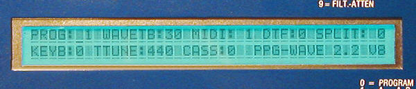
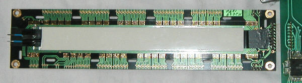
| EL Backlight Retrofit for the Wave 2.2One of the improvements of the Wave 2.3 over its predecessor was the backlit display, which makes it much easier to operate the Wave in a dimly lit environment. As I recently discovered, it is possible to add this feature to older Waves, too. Here's how. Attention: the description given here is valid for earlier types of the Wave 2.2. To find out the display type of your Wave, just look at the first photo. If the lower right corner of the display ends above the white "P" of the "0 = PROGRAM" text printed below it, you have one of the later models with a(n originally) backlit display; please refer to this page for that kind of Wave. If it ends above the "G" or "R", you have an older model with exactly the kind of display I'm describing here.
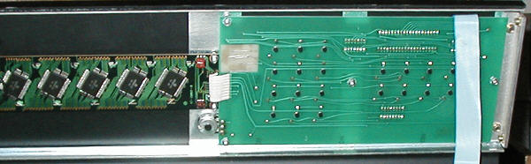
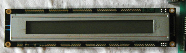
Another way to determine the display type is to open up the Wave and look at
the TAS board and LCD display from below. The old-style displays look like that:
And yet another Attention:To add backlight to your Wave 2.2's (presumably valid for Wave 2, too, but I've got to test that yet :-) display, you need to go really really deep into the device's innards - be warned! In contrast to the Wave 2.3's, the displays used in the earlier machines can't be found any more, so greatest care and attention is needed! Background InformationIn the meantime, there are quite some companies that craft EL Foils to customer specifications; this - and the successful replacement of my newer Waves' displays - gave me the idea to upgrade my older machines, too. In theory, it should be relatively easy, shouldn't it? Right... and wrong. For one, it's possible to get EL Foils in the required size, but to get them for a decent price is detective's work. Ah well, it took some time, but now I got some. Second point - the Wave display just isn't laid out for backlight. My first attempt didn't work at all... there's a reflective foil behind the display that reflects the polarized environmental light so that you can read the text. This foil is completely opaque - a backlight foil behind it has no chance. PrerequisitesThe following description requires some parts. These are:
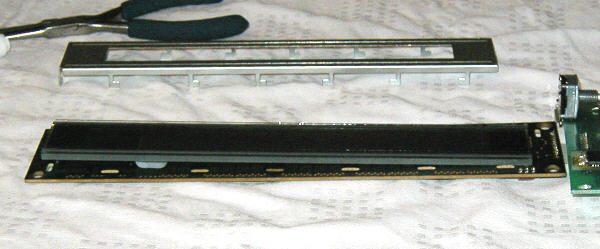
This list has been compiled under the assumption that the backlight foil control should closely resemble that of the Wave 2.3; there's a lot of different inverters on the market, there are even some that should work directly with the +5V that go from the TAS board to the LCD display. One fine day I'm going to try that :-) Part 1 - Display RedesignAs I've already said, the display needs a lot of work. The reflective foil
must be removed to let the backlight foil do its job. First, the metal cover has
to be removed from the display and then the display itself has to be carefully
disassembled. After having disassembled the display, you can carefully remove the
reflective foil. You really need to be careful - below the reflector foil,
there's a polarizing foil; if you accidentially remove that, too, the display is
dead. Gone. Then, the EL foil can be fixed on the PCB - ab-so-lute-ly exactly centered, of course :-) with just a little bit of glue. I'd recommend to put the EL foil's contacts onto the far side of the display, seen from the TAS board. Also, make sure the contacts are isolated the full way under the metal hood.
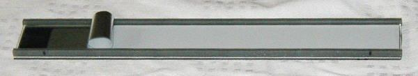
Now put the glass part of the display into its former position (you did place a mark or two, didn't you? :-), put the metal hood over it and bend the little legs of the metal hood back into place. The pressure of the metal hood reestablishes the contact between the PCB and the display; if the display has been placed exactly in the right position, it should work just like before the operation. If some lines or columns are missing, or it doesn't work altogether, reopen it and correct the alignment.
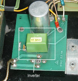
Of course, that's only the first round of the game... by now, we have a display that looks and works just like it did before, just with two additional contacts protruding on one side that just beg to be soldered to... yeah, to what? Part 2 - The InverterAs you can read elsewhere, the EL foil needs approx. 100V AC with about 400 Hz to work. In the Wave 2.3, this is provided by an inverter that sits on the PSU PCB: Since the Wave 2.2 doesn't have such a PCB, the logic needs to be recreated. Fortunately, it's a very simple one:
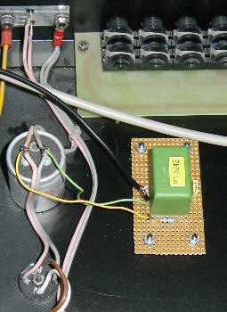
... and that's how it looks like in my Wave, done on a strip board and bolted into the Wave:
... quite plain, isn't it? The result after turning the thing on can be admired at the very start of this page :-) Requests, anyone?If somebody wants to upgrade his/her old Wave, but doesn't really want to go through the hassle him/herself, just contact me.
|